
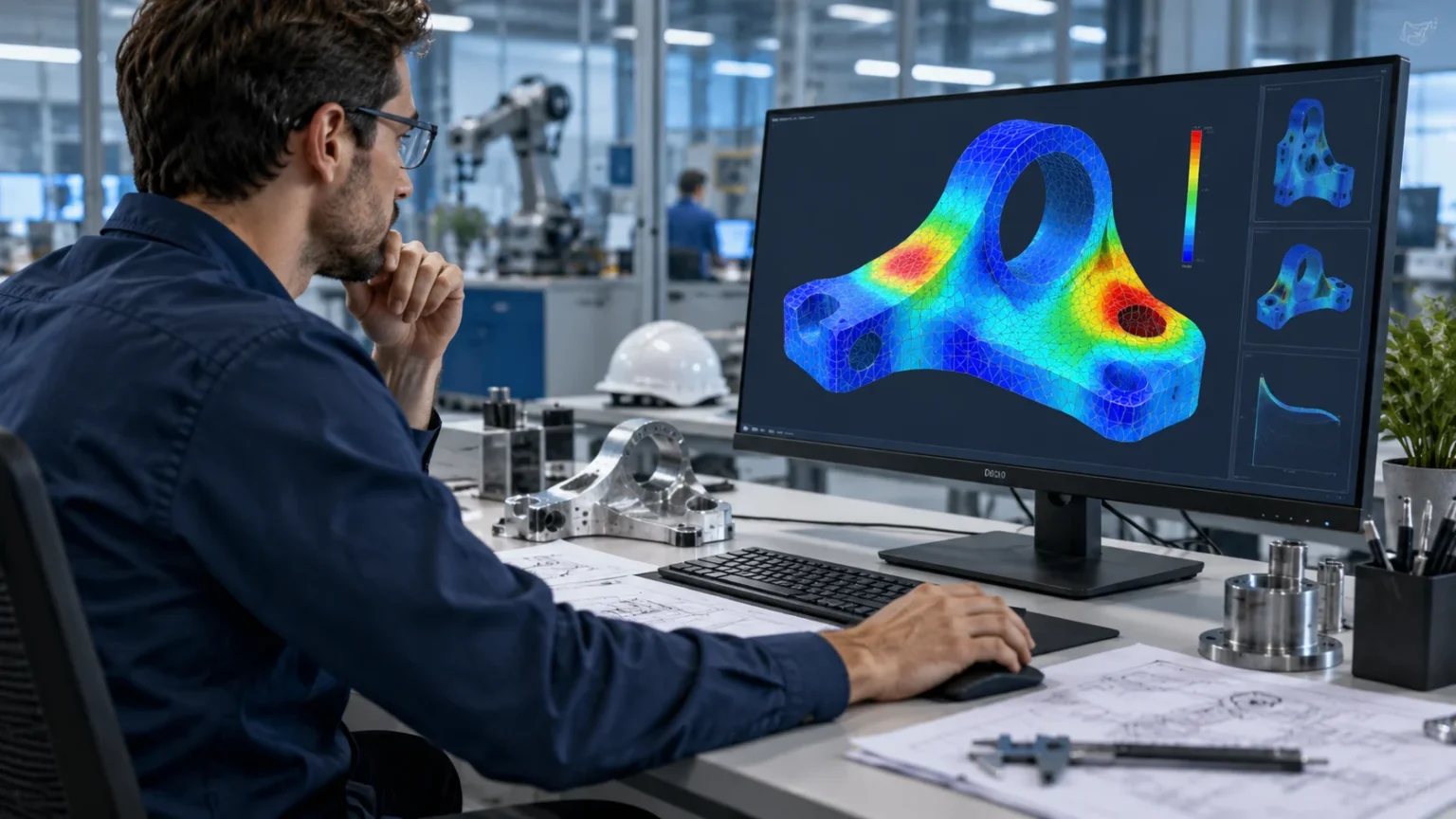

FEA Meaning: Finite Element Analysis Explained
FEA stands for Finite Element Analysis, a computer-based engineering method used to predict how objects and structures behave under real-world conditions. Engineers use it to study stress, deformation, vibration, heat transfer, fluid effects, and other physical responses before building or testing a final product. Instead of relying only on physical prototypes, FEA allows a complex design to be divided into many smaller pieces that can be analyzed mathematically. These smaller pieces are called finite elements, and together they form a computational model of the original object. The method can reveal areas that may bend, overheat, vibrate, or fail under particular conditions. This makes FEA an important tool in modern engineering design and product development.
Finite element analysis is widely used because many engineering problems are too complicated to solve accurately with simple hand calculations. Real components often contain curved surfaces, holes, joints, changing thicknesses, multiple materials, and irregular loading conditions. These features make traditional formulas difficult or impossible to apply across the entire structure. FEA addresses the problem by dividing the geometry into smaller regions where the governing equations can be solved more practically. Computers then combine the results from all of these regions to estimate the behavior of the complete system. This approach makes it possible to analyze everything from small mechanical parts to bridges, aircraft structures, medical devices, and industrial machinery.
Modern FEA software has made simulation more accessible to engineers across many industries, but the technology still requires careful judgment. Creating a colorful stress plot does not automatically mean the analysis is accurate or useful. Engineers must select appropriate materials, loads, boundary conditions, mesh sizes, contact definitions, and mathematical models before solving the problem. Incorrect assumptions can produce results that appear convincing while failing to represent real behavior. For that reason, understanding the fundamentals of finite element analysis is more important than simply knowing how to operate simulation software. Reliable FEA combines engineering knowledge, numerical methods, and thoughtful interpretation of results.
The growing use of digital product development has made finite element simulation even more valuable. Companies increasingly want to reduce development time, optimize materials, improve product performance, and identify problems before expensive prototypes are manufactured. FEA can support these goals by allowing engineers to test multiple design variations virtually. A component can be made thinner, stronger, lighter, or more heat resistant in the simulation before physical changes are made. Engineers can also explore unusual loading scenarios that may be difficult or costly to reproduce repeatedly in a laboratory. Used correctly, finite element analysis can therefore improve both design efficiency and engineering confidence.
This guide explains FEA meaning in straightforward language while covering the concepts needed to understand how finite element analysis works. You will learn about meshes, nodes, elements, material properties, boundary conditions, loads, solvers, and post-processing. The guide also explores different types of FEA, including structural, thermal, dynamic, nonlinear, and fatigue analysis. Practical examples show how the method is used in automotive, aerospace, civil, manufacturing, and other engineering fields. You will also learn about the benefits and limitations of FEA and why verification remains important. By the end, you should understand both what FEA is and how engineers use it to make better design decisions.
What Does FEA Mean?
FEA means Finite Element Analysis, which is the practical application of the finite element method to solve engineering and physical problems using numerical calculations. The basic idea is to break a complicated object or domain into many smaller, manageable regions called elements. Each element follows mathematical equations that approximate how that small region behaves under applied conditions. The computer solves the equations across the entire collection of elements and combines the results into a representation of the full model. Engineers can then review outputs such as displacement, stress, strain, temperature, or vibration. This process turns a difficult continuous engineering problem into a large but solvable set of smaller numerical problems.
The term finite refers to the fact that the model is divided into a limited number of individual elements rather than treated as one continuous object. These elements are connected at points known as nodes, which allow forces, temperatures, displacements, and other quantities to pass through the model. Depending on the problem, elements can take different shapes, including lines, triangles, quadrilaterals, tetrahedrons, and hexahedrons. More elements generally allow the model to represent complex geometry and changing behavior more closely, although they also increase computational cost. The collection of elements is called a finite element mesh. Mesh quality becomes one of the most important factors affecting the reliability and efficiency of an FEA simulation.
Finite element analysis is particularly useful when geometry or loading conditions make analytical solutions difficult. A simple beam with a uniform cross-section may be evaluated using standard engineering formulas, but a complex bracket with multiple holes and curved surfaces presents a much harder problem. FEA can model the actual shape and determine how stresses vary throughout it. The same approach can be extended to components with several materials, complicated support conditions, or localized forces. Engineers can therefore study designs that would otherwise require extensive physical testing. This flexibility explains why FEA has become a standard part of many computer-aided engineering workflows.
FEA does not replace engineering theory because the simulation still depends on fundamental physical laws. Structural analysis may use equations describing equilibrium, material behavior, and deformation, while thermal analysis uses equations governing heat transfer. The finite element method provides a numerical technique for applying those laws to complex shapes and conditions. Engineers still need to understand whether the assumptions behind the mathematical model are appropriate for the real system. For example, a linear material model may be unsuitable if a component experiences permanent plastic deformation. Accurate simulation therefore depends on matching the numerical model to the actual physical behavior being studied.
People sometimes confuse FEA with general computer simulation, but FEA is a specific numerical approach within the wider field of engineering analysis. Computer simulation may include computational fluid dynamics, multibody dynamics, electromagnetic analysis, system modeling, and many other methods. Finite element analysis is especially associated with structural mechanics, although it can also be used for thermal, acoustic, electromagnetic, and multiphysics problems. The exact capabilities depend on the software and mathematical formulations available. Understanding this distinction helps explain why engineers may combine FEA with other simulation tools. Complex products often require several different analysis methods to understand how multiple physical effects interact.
How Finite Element Analysis Works
The FEA process usually begins with geometry representing the object or system that needs to be analyzed. Engineers may create this geometry directly inside simulation software or import it from a computer-aided design program. The model might represent a complete assembly, a simplified component, or only the region relevant to the engineering question. Simplification is often important because unnecessary cosmetic details can dramatically increase mesh size without improving useful results. Small fillets, logos, threads, or holes may sometimes be removed when they do not affect the behavior being studied. A well-prepared geometry model allows the simulation to focus computational effort on the features that actually matter.
After preparing the geometry, engineers assign material properties that describe how each part responds to physical conditions. Structural simulations may require values such as Young’s modulus, Poisson’s ratio, density, yield strength, and thermal expansion coefficient. Thermal simulations may use conductivity, specific heat, and density, while nonlinear analyses can require detailed stress-strain curves. Different materials behave differently, so choosing realistic values is essential for meaningful results. Steel, aluminum, plastic, rubber, and composites cannot be treated as interchangeable simply because they share similar geometry. Material data should also reflect relevant temperature ranges and manufacturing conditions whenever those factors significantly affect performance.
The next stage involves applying loads and boundary conditions to represent how the real object interacts with its environment. A load might be a force, pressure, torque, acceleration, temperature, heat flux, or another physical input. Boundary conditions describe constraints or known conditions, such as a fixed mounting surface or a specified temperature. These definitions can strongly influence the solution because they determine how the model is allowed to move or respond. Overly rigid constraints may create unrealistic stress concentrations, while missing supports can allow the model to move freely. Careful boundary-condition selection is therefore one of the most important engineering decisions in finite element modeling.
Once geometry, materials, and conditions are defined, the model is divided into finite elements through a process called meshing. The software creates a network of nodes and elements that approximates the original geometry. Smaller elements can usually capture local variations more accurately, particularly near holes, corners, contacts, and other regions where stress changes quickly. However, using an extremely fine mesh everywhere can make calculations unnecessarily slow and memory intensive. Engineers often use finer mesh regions only where detailed results are required. Mesh refinement studies can then determine whether results remain stable as element size decreases, helping establish that the solution is not overly dependent on the chosen mesh.
The final calculation stage is handled by a numerical solver that assembles and solves the mathematical equations generated by the model. Depending on the analysis, the solver may calculate displacement, temperature, natural frequencies, stress, strain, contact pressure, or other quantities. Once the solution is complete, engineers review the results during a stage known as post-processing. Software commonly presents results as contour plots, graphs, animations, tables, and numerical summaries. Engineers then compare these outputs with design requirements, physical expectations, hand calculations, or test data. The objective is not simply obtaining a result but determining whether the result makes engineering sense and supports a defensible design decision.
Key Components of an FEA Model
The mesh is one of the most recognizable components of a finite element model because it determines how the original geometry is broken into smaller regions. A mesh can contain thousands or even millions of elements depending on the size and complexity of the problem. Coarser meshes solve faster but may fail to capture localized behavior accurately. Very fine meshes can improve resolution but increase processing time and computer memory requirements considerably. Engineers therefore aim for an efficient balance rather than automatically using the smallest possible element size. Strategic mesh refinement near critical areas often delivers accurate results while keeping the overall computational model practical.
Nodes are points within the mesh where important unknown quantities are calculated or connected between elements. In structural analysis, nodal quantities commonly include displacement, while stresses and strains may be calculated within elements and then displayed across the mesh. Nodes create continuity between neighboring elements so the complete model behaves as one connected structure. Their arrangement is determined by the selected element type and meshing strategy. Higher-order elements may include additional nodes along their edges or inside their volume, allowing them to represent curved behavior more accurately. Understanding nodes is useful because many loads, supports, and result quantities are ultimately interpreted through nodal behavior.
Elements are the individual mathematical regions that make up the finite element mesh. Different element formulations are suited to different types of geometry and physical behavior. Beam elements can efficiently represent long, slender members, while shell elements are useful for thin plates, sheet metal, and surface-like structures. Solid elements are commonly used for three-dimensional components where stresses vary throughout the volume. Choosing the wrong element type can create unnecessary computational cost or reduce accuracy. Experienced analysts therefore select elements based on geometry, expected deformation, thickness, loading, and the engineering question being investigated rather than simply accepting default software settings.
Material models describe the relationship between loads and the resulting response inside each element. A basic linear elastic material assumes deformation changes proportionally with applied stress and disappears when the load is removed. More advanced models can represent plastic deformation, rubber-like behavior, creep, composite materials, damage, and other complex responses. Nonlinear material behavior becomes especially important when a product operates beyond the range where simple elastic assumptions remain valid. Accurate material modeling can require experimental test data rather than generic handbook values. Because the solver follows the material equations provided, unrealistic material properties can produce unrealistic results even when every other part of the FEA model is carefully constructed.
Contacts, connections, loads, and constraints complete the physical definition of many finite element models. Assemblies may contain bolted joints, welded regions, bearings, frictional interfaces, bonded surfaces, or components that separate during loading. Each interaction can affect how forces travel through the structure and where stresses develop. Software offers different contact formulations to represent these situations, but they must be selected thoughtfully. A bonded contact may be appropriate for a welded interface but misleading for two surfaces that should slide. Accurate FEA therefore depends on representing not only individual parts but also the mechanical relationships that connect those parts into a functioning system.
Different Types of FEA
Linear static structural analysis is one of the most common types of finite element analysis and is often the starting point for engineering simulations. It predicts how a structure responds to loads that are assumed to remain constant or change slowly enough that dynamic effects can be ignored. Engineers typically examine displacement, stress, strain, and reaction forces from the resulting solution. The analysis assumes relatively small deformation and usually treats material behavior as linear elastic. These assumptions make the calculations efficient and suitable for many everyday engineering problems. Brackets, frames, housings, supports, machine parts, and numerous other components can often be evaluated effectively using linear static FEA.
Nonlinear FEA is used when the relationship between loads and structural response cannot be represented accurately with simple linear assumptions. Nonlinearity can arise from material behavior, large deformation, changing contact conditions, or combinations of these effects. A rubber seal, for example, may deform significantly and therefore require a nonlinear material model. Metal components loaded beyond their elastic limit may require plasticity models to estimate permanent deformation. Contact between moving surfaces can also create nonlinear behavior because the contact area changes as loads are applied. Nonlinear simulations usually require more computational effort and careful solver settings, but they can represent real behavior that linear analysis would miss.
Dynamic analysis examines behavior when time-dependent forces, inertia, and vibration become important. Modal analysis identifies natural frequencies and mode shapes, helping engineers understand how structures prefer to vibrate. Harmonic analysis can evaluate the response to repeated sinusoidal loading, while transient dynamic analysis studies events that change over time. These methods are useful for machinery, vehicles, aerospace structures, electronics, buildings, and equipment exposed to vibration or impact. Avoiding resonance is often a major goal because operating near a natural frequency can significantly amplify movement and stress. Dynamic FEA therefore helps engineers design structures that remain reliable under conditions that static calculations cannot fully represent.
Thermal FEA evaluates how heat moves through components and how temperatures develop under specific conditions. Engineers can model conduction through solids, applied heat sources, convection at surfaces, radiation, and changing environmental temperatures. The resulting temperature distribution can then be used independently or transferred into structural analysis. This is valuable because temperature changes can cause materials to expand, contract, soften, or develop thermal stresses. Electronics, engines, batteries, heat exchangers, industrial equipment, and manufacturing processes frequently require thermal simulation. Coupled thermal-structural analysis allows engineers to study how heat and mechanical loads interact, providing a more realistic picture of performance in temperature-sensitive applications.
Fatigue, buckling, fracture, acoustic, and multiphysics analyses extend FEA into additional engineering problems. Fatigue analysis estimates how repeated loading may lead to failure even when individual loads remain below the material’s immediate strength limit. Buckling analysis studies instability in slender or thin structures under compressive loading. Fracture mechanics can evaluate crack behavior and stress intensity near existing defects. Acoustic analysis may study vibration-generated sound, while multiphysics simulation connects structural, thermal, electromagnetic, or fluid effects. These specialized approaches demonstrate that finite element analysis is not a single calculation method. It is a broad numerical framework that can be adapted to many physical phenomena encountered in modern engineering.
Step-by-Step FEA Process
The first step in a reliable FEA study is defining the engineering question before opening simulation software. Analysts should understand what they need to predict, which failure modes matter, and what level of accuracy the decision requires. A simulation designed to estimate overall deflection may need a different model from one intended to study stress around a tiny notch. Clear objectives also help determine whether a two-dimensional, shell, beam, or full three-dimensional representation is appropriate. Without a focused question, models often become unnecessarily complicated and difficult to validate. Good finite element analysis begins with engineering judgment rather than software settings, because the model should always serve a specific design decision.
Geometry preparation comes next and often involves simplifying the computer-aided design model before meshing. Real CAD files may contain tiny holes, decorative fillets, logos, fastener threads, and other details that dramatically increase element count. Analysts decide which details influence the desired results and which can safely be removed or simplified. Symmetry may also allow only part of a component to be modeled, reducing computational effort while preserving relevant physical behavior. Thin parts can sometimes be replaced by shell representations instead of being meshed with many solid elements through their thickness. Effective simplification can improve solver performance without sacrificing the engineering information needed from the analysis.
The analyst then defines materials, connections, supports, loads, and other conditions that represent the real operating environment. This stage requires careful interpretation because physical conditions rarely map perfectly to simple software options. A bolted joint, for example, might require preload, friction, or contact rather than a fully fixed connection. Pressure may vary across a surface instead of remaining uniform, and a support may allow motion in some directions while restricting others. Choosing conditions based only on convenience can produce misleading results. Analysts should therefore ask how forces actually enter, travel through, and leave the structure. Representing the load path realistically is essential for meaningful finite element results.
Meshing follows after the physical model has been established, but mesh quality should be evaluated rather than accepted automatically. Regions with rapidly changing geometry or high stress gradients usually require smaller or higher-quality elements. Long, regular regions may tolerate larger elements without losing important information. Analysts often perform a mesh convergence study by refining the mesh and observing whether critical results stabilize. If a stress value changes dramatically every time the mesh is refined, the initial result may not yet be sufficiently reliable. Mesh convergence does not guarantee that the complete model is correct, but it removes one important source of numerical uncertainty. Efficient meshing is therefore both a technical skill and an engineering judgment.
After solving the model, results must be interpreted, checked, and communicated carefully. Analysts should review deformed shapes, reaction forces, stress patterns, contact behavior, and other outputs to see whether they match physical expectations. Extremely high localized stresses may result from mathematical singularities rather than true material failure, especially near sharp corners or idealized constraints. Comparing the solution with hand calculations, simplified analytical models, previous tests, or experimental measurements can increase confidence. Engineers should also document assumptions and limitations so others understand what the model does and does not prove. FEA is most valuable when results lead to clear engineering conclusions rather than simply producing visually impressive contour plots.
Where FEA Is Used in Real-World Engineering
The automotive industry uses finite element analysis extensively when developing vehicles and individual components. Engineers can analyze chassis structures, suspension parts, engine components, wheels, seats, brackets, battery housings, and many other systems. Structural simulations help predict how parts respond to operating loads, while vibration analysis can identify potential resonance problems. Thermal analysis is increasingly important for electronics, batteries, braking systems, and powertrain components. FEA can also support crash-related structural studies when advanced nonlinear models are used. By evaluating designs virtually before building multiple prototypes, automotive teams can reduce development cycles while improving weight, performance, durability, and safety.
Aerospace engineering relies heavily on FEA because aircraft and spacecraft structures must combine low weight with high strength and reliability. Wings, fuselage sections, landing gear, engine components, satellites, and internal structures may all undergo detailed simulation. Engineers can study pressure loading, vibration, thermal expansion, fatigue, buckling, and other conditions encountered during operation. Composite materials add additional complexity because their behavior depends on fiber orientation and layered construction. Finite element models help designers understand these effects before expensive manufacturing and testing programs begin. Because aerospace structures operate under demanding conditions, simulation is generally combined with strict verification, validation, and physical testing rather than being treated as a standalone source of evidence.
Civil and structural engineers use finite element methods to study buildings, bridges, towers, foundations, tunnels, dams, and other large structures. Simple structures can often be designed using traditional calculations, but irregular geometry and complex loading may require more advanced numerical models. FEA can estimate deformation, internal forces, stress distribution, vibration behavior, and buckling under different load combinations. Engineers may model wind, traffic, gravity, seismic effects, soil interaction, or temperature changes depending on the project. Beam, shell, and solid elements allow structures to be represented at different levels of detail. These simulations help engineers understand structural behavior while supporting design decisions that still need to follow applicable engineering standards.
Manufacturing companies use FEA both to evaluate finished products and to understand what happens during production processes. Forming, stamping, forging, extrusion, machining, and welding can introduce stresses and deformation that affect final part quality. Simulation can help predict whether sheet metal will wrinkle, whether a formed part will spring back, or whether welding will distort an assembly. Molded plastic components may also be evaluated for structural performance after manufacturing conditions are considered. Engineers can compare design alternatives before expensive tooling is produced. This connection between product design and manufacturing simulation helps companies reduce trial-and-error development while identifying problems earlier in the production cycle.
FEA is also used in medical devices, electronics, energy systems, consumer products, robotics, and many other fields. Medical engineers may analyze implants, prosthetic devices, surgical tools, or equipment exposed to repeated loading. Electronics designers can examine thermal performance, solder-joint stress, vibration, and enclosure strength. Wind turbines, pipelines, pressure vessels, and renewable energy equipment can be evaluated under operational and environmental loads. Consumer product teams may use FEA to reduce material while maintaining adequate stiffness and durability. The wide range of applications shows that finite element analysis is useful wherever physical products must resist forces, temperature, vibration, or deformation during real-world use.
Benefits and Limitations of Finite Element Analysis
One of the biggest benefits of FEA is the ability to evaluate designs before manufacturing physical prototypes. Engineers can identify potentially weak regions, excessive deformation, thermal problems, or vibration concerns while changes are still relatively easy to make. Multiple design concepts can be simulated and compared without producing a separate physical part for every variation. This can reduce development time and help teams focus expensive testing on more promising designs. Virtual analysis is particularly valuable when prototypes require specialized tooling or expensive materials. FEA does not eliminate physical testing, but it can make the overall development process more targeted and efficient by exposing obvious design issues earlier.
FEA also supports design optimization by showing where material is carrying useful load and where it may be unnecessary. An engineer might discover that a component contains excess material in low-stress regions while another area requires reinforcement. Geometry can then be adjusted to reduce weight without sacrificing the required structural performance. This is especially valuable in aerospace, automotive, robotics, and portable products where mass strongly affects efficiency or usability. Simulation can also compare alternative materials, thicknesses, rib patterns, and support locations. By repeating these studies systematically, teams can improve performance before committing to final production. Modern optimization tools increasingly combine finite element solvers with automated design exploration.
Another benefit is the amount of detailed information FEA can provide throughout a component. Physical testing may measure strain or displacement at selected sensor locations, while a finite element model can display estimated results across the entire geometry. Engineers can examine internal regions that would be difficult to instrument during a real test. They can also explore hypothetical scenarios involving unusual loads or environmental conditions. This broad visibility can improve understanding of how a product behaves rather than simply determining whether it passed one particular test. However, the apparent detail of simulation results should not be confused with guaranteed accuracy. Every displayed value remains dependent on the assumptions and quality of the underlying model.
The main limitation of FEA is that a model is only an approximation of reality. Engineers must simplify geometry, estimate loads, select material models, define connections, and make assumptions about boundary conditions. If these choices do not represent real behavior, the solver can still produce a mathematically consistent but physically misleading answer. Software cannot automatically know whether an assumed support is unrealistic or whether a material property is inappropriate. This is why experienced analysts spend considerable effort checking inputs instead of focusing only on results. Finite element analysis should therefore be treated as an engineering model that supports judgment rather than an unquestionable prediction of exactly what will happen.
Computational cost and interpretation challenges create additional limitations, particularly for advanced simulations. Large nonlinear models with detailed contact, complex materials, and millions of elements may require substantial processing power and solver time. Convergence problems can occur when the numerical algorithm struggles to find a stable solution. Highly detailed results can also encourage false precision if users report numbers beyond what the model assumptions can justify. Training and experience are therefore important when FEA is used for safety-critical or expensive decisions. The best practice is to combine simulation with analytical checks, engineering experience, and appropriate testing. FEA becomes most powerful when it forms one part of a broader verification process.
How to Improve FEA Accuracy and Reliability
Improving finite element accuracy begins with understanding the real engineering problem rather than simply refining the mesh. A model with millions of perfect elements can still be wrong if the applied loads do not represent actual operating conditions. Analysts should first confirm the load paths, supports, material behavior, contacts, and relevant failure modes. They should also decide what level of accuracy is truly required for the decision being made. A preliminary design study may tolerate broader assumptions than a final safety-critical assessment. Clearly defining uncertainty helps prevent unnecessary modeling complexity while keeping attention focused on inputs that have the strongest influence on the results.
Mesh convergence is one of the most common techniques for increasing confidence in FEA results. The analyst solves the model using an initial mesh and then gradually refines important regions while monitoring selected outputs. If displacement, reaction force, or relevant stress values remain relatively stable as the mesh becomes finer, the solution may be considered less sensitive to element size. Local stress singularities require special care because their values may continue increasing indefinitely with refinement. Analysts should therefore understand whether the quantity being monitored is physically meaningful. Mesh convergence provides valuable numerical evidence, but it must be interpreted alongside engineering knowledge rather than treated as an automatic guarantee of accuracy.
Verification is the process of checking whether the numerical model has been solved correctly according to the chosen mathematical assumptions. Simple hand calculations or analytical solutions can provide valuable benchmarks for selected parts of a model. Reaction forces can be checked against applied loads to confirm equilibrium, and symmetry can be used to see whether results behave as expected. Analysts should inspect deformed shapes because unexpected movement often reveals missing constraints or incorrect connections. Solver warnings also deserve attention rather than being ignored simply because a result file was produced. These checks can identify modeling mistakes before the results are used in design decisions. Verification asks whether the numerical problem was solved correctly.
Validation addresses a different question by asking whether the model accurately represents physical reality. Engineers may compare FEA predictions with strain gauge measurements, load tests, thermal measurements, vibration data, or other experimental results. Agreement between simulation and testing can increase confidence that the assumptions capture the important physical behavior. Differences can reveal incorrect material data, unknown contact conditions, manufacturing variation, or loads that were estimated inaccurately. Validation is particularly important when models will be used repeatedly for related designs or safety-sensitive decisions. A validated modeling approach becomes much more valuable because engineers understand where it performs well and where limitations remain. Physical evidence therefore complements numerical sophistication.
Good documentation also improves the reliability of FEA because it allows assumptions and decisions to be reviewed by others. A useful analysis report should describe geometry simplifications, materials, element types, mesh quality, boundary conditions, applied loads, contact assumptions, solver settings, and important results. It should explain why particular modeling choices were made instead of displaying screenshots without context. Limitations and uncertainties should also be stated clearly, especially when results depend strongly on estimated inputs. Peer review can identify issues that the original analyst may overlook. Transparent documentation turns FEA from an isolated computer exercise into a repeatable engineering process that can support future design changes and informed decision-making.
Frequently Asked Questions
What does FEA stand for?
FEA stands for Finite Element Analysis. It is a numerical engineering method used to predict how structures, components, and physical systems respond to forces, heat, vibration, deformation, and other operating conditions.
What is the main purpose of finite element analysis?
The main purpose of FEA is to estimate how a design will behave before or alongside physical testing. Engineers use it to identify stress concentrations, excessive deformation, thermal problems, vibration risks, and other potential performance issues.
What is a mesh in FEA?
A mesh is the network of small finite elements used to represent the geometry being analyzed. These elements are connected through nodes, allowing the solver to approximate how the complete structure responds to applied loads and conditions.
Is FEA accurate?
FEA can provide highly useful and accurate predictions when the geometry, materials, loads, boundary conditions, mesh, and mathematical assumptions represent the real system appropriately. Its accuracy depends heavily on modeling quality, verification, validation, and the engineering judgment used to interpret the results.
What industries use FEA?
FEA is widely used in automotive, aerospace, civil engineering, manufacturing, energy, electronics, robotics, medical devices, and consumer product development. Any industry that designs components affected by loads, heat, vibration, deformation, or structural performance can potentially benefit from finite element analysis.