
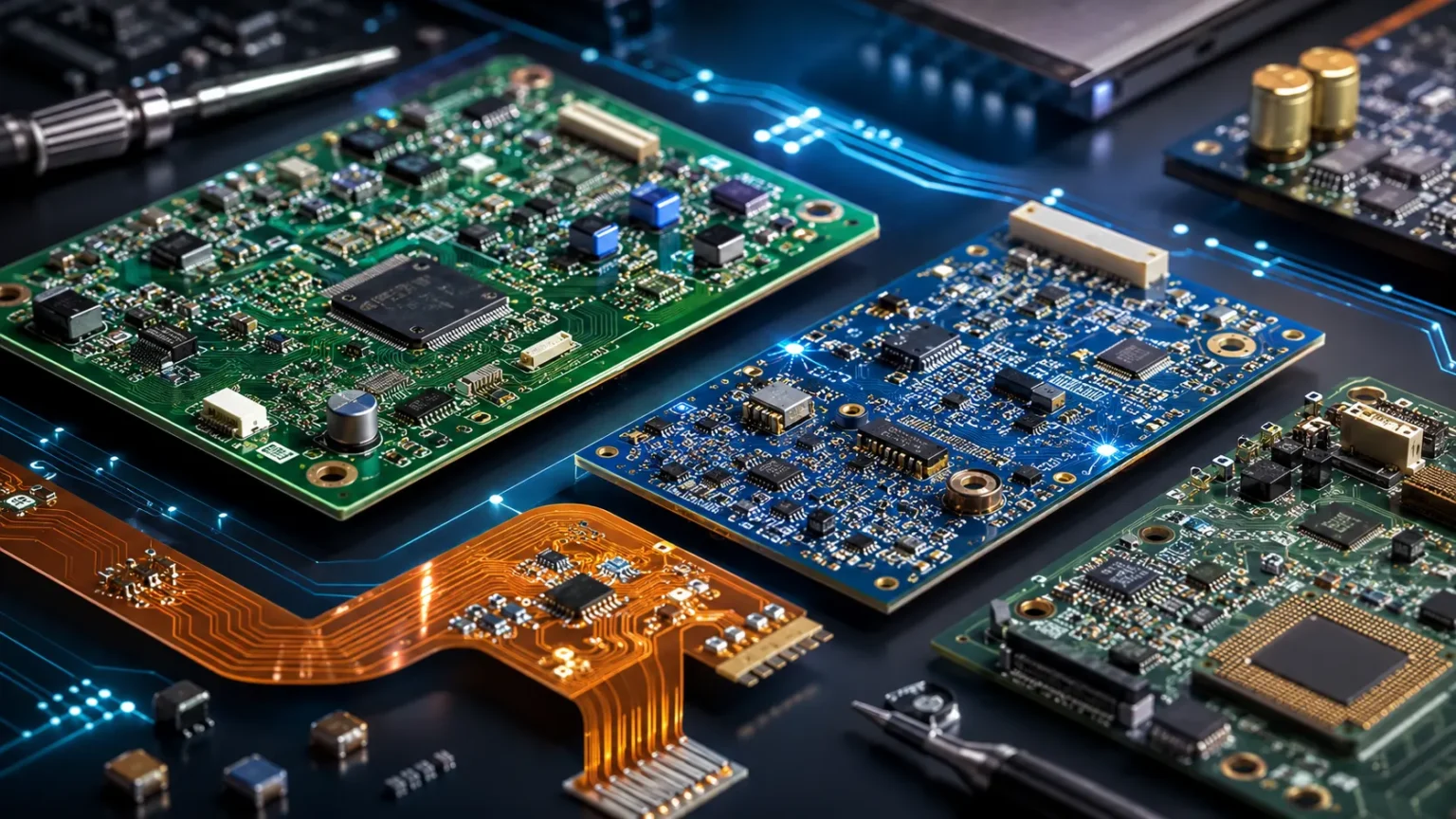

Circuit Boards: How They Work, Types & Components
Circuit boards are at the heart of nearly every modern electronic device, from smartphones and laptops to washing machines, medical equipment, cars, and industrial control systems. A circuit board provides a structured way to connect electronic components so electricity and signals can move through a device in a controlled manner. Instead of using loose wires to join every component individually, manufacturers use conductive pathways built directly into a flat board. These pathways guide current between processors, resistors, capacitors, connectors, sensors, and other parts. The most common form is the printed circuit board, usually shortened to PCB. Understanding how circuit boards work makes many everyday technologies easier to appreciate.
A circuit board may look like a simple green panel covered with small components, but its internal structure can be surprisingly complex. Conductive copper traces act like tiny roads that carry electrical power and data between different parts of the circuit. Insulating layers keep signals separated where necessary, while drilled holes and metal connections can link one side of the board to another. Components are attached using solder, creating both electrical and mechanical connections. Some circuit boards contain only a few simple parts, while advanced computer boards may contain thousands of interconnected components. The design depends entirely on what the electronic system needs to accomplish.
Printed circuit boards come in several types, including single-sided, double-sided, multilayer, rigid, flexible, and rigid-flex designs. A simple electronic toy might use a single-sided board because its circuit requires relatively few connections. A smartphone or computer motherboard needs multiple internal layers because enormous numbers of signals must travel through a limited amount of space. Flexible circuit boards can bend around tight spaces, while rigid-flex designs combine stable sections with bendable connections. Different PCB types allow engineers to balance cost, size, durability, performance, and manufacturing complexity. Choosing the right board architecture is therefore an important part of electronic product design.
The components mounted on a circuit board each perform specific functions. Resistors control electrical current, capacitors store small amounts of electrical energy, diodes guide current in particular directions, and transistors can switch or amplify signals. Integrated circuits contain many microscopic electronic functions inside a single package, allowing complex computing and control to fit into very small spaces. Connectors allow the board to communicate with batteries, displays, motors, sensors, or other circuit boards. The board itself organizes these components into a functional electronic system. Without the carefully designed connections between them, the individual parts would have little practical value.
Modern circuit board technology continues to become smaller, faster, and more sophisticated as electronics evolve. High-density interconnect designs, advanced materials, smaller surface-mount components, and automated manufacturing allow engineers to fit greater functionality into compact products. At the same time, circuit boards must handle challenges such as heat, electromagnetic interference, vibration, moisture, and high-speed data transmission. Designing a reliable PCB therefore involves electrical engineering, mechanical considerations, manufacturing knowledge, and careful testing. The sections below explain how circuit boards work, the major PCB types, important components, manufacturing methods, and common applications in clear and practical terms.
What Is a Circuit Board?
A circuit board is a physical platform that supports and electrically connects components used to create an electronic circuit. In most modern products, the circuit board is a printed circuit board made from insulating material with patterned conductive copper pathways. These pathways replace much of the manual wiring that would otherwise be needed between components. The board gives the electronic system a compact, repeatable, and organized structure. It also holds components securely in fixed positions. This makes mass production far more practical than assembling complex devices with individual wires.
The base material of a typical PCB is called the substrate. One common material is fiberglass-reinforced epoxy laminate, often identified by terms such as FR-4. The substrate provides mechanical strength while electrically separating conductive areas. Thin copper sheets are bonded to the substrate and later patterned into traces, pads, and other electrical structures. Protective coatings can then be added over the copper. Different substrate materials may be used when circuits need special thermal, mechanical, or high-frequency properties.
Copper traces form the electrical pathways visible on many circuit boards. They carry power and signals from one component to another according to the circuit design. Trace width, thickness, spacing, and routing all influence electrical behavior. A power trace carrying substantial current may need to be wider than a delicate signal trace. High-speed data lines can require precise geometry to maintain signal quality. Engineers therefore design PCB traces carefully rather than simply drawing the shortest possible connection between components.
Pads are exposed areas of copper where components are soldered to the board. Some components have wire leads that pass through holes before being soldered, while modern surface-mount parts attach directly to pads on the board’s surface. Vias are small plated holes that create electrical connections between different copper layers. In multilayer boards, vias allow signals to move vertically through the PCB structure. Together, traces, pads, and vias create the interconnected network required by the electronic design. Their arrangement is produced from a digital PCB layout created by engineers.
A completed circuit board is therefore much more than a support panel. It combines electrical connections, mechanical mounting, signal routing, and sometimes thermal management into one engineered structure. The board may distribute power, process sensor signals, control motors, store data, communicate wirelessly, or perform thousands of other functions depending on the components installed. A bare PCB without components mainly provides the connection infrastructure. Once components are assembled onto it, the board becomes part of a functioning electronic system. This distinction helps explain why PCB design and electronic circuit design are closely linked but not identical.
How Do Circuit Boards Work?
Circuit boards work by creating controlled pathways through which electrical current and electronic signals can travel. A power source such as a battery or external supply introduces electrical energy into the circuit. Copper traces then distribute that energy to the components that require it. Components modify, control, store, or respond to electrical signals according to their function. Other traces carry the resulting signals to additional components. The repeated interaction between components and connections allows the circuit to perform useful tasks.
Consider a simple LED circuit as an example. A power source provides voltage, while copper traces connect the source to a resistor and light-emitting diode. The resistor limits current so the LED does not receive more electricity than it can safely handle. Current then passes through the LED, causing it to emit light, before returning through the circuit path. On a printed circuit board, these connections are formed by copper rather than separate loose wires. Even this simple example shows how the board creates predictable electrical relationships between components.
More advanced boards process signals rather than merely allowing current to flow. A sensor may convert temperature, pressure, motion, light, or sound into an electrical signal. The circuit board routes that signal to an integrated circuit or microcontroller for processing. The processor may compare the measurement with programmed instructions and then send another signal to a display, motor, alarm, or communication device. This process can happen thousands or millions of times per second. Modern electronics therefore depend on both electrical pathways and carefully programmed logic.
Power distribution is another important function of many circuit boards. Different components may require different voltages or levels of electrical current. Voltage regulators, power-management integrated circuits, capacitors, and inductors can help convert and stabilize incoming power. Dedicated copper areas called power planes may distribute electricity efficiently across multilayer boards. Ground planes provide low-resistance return paths and can also improve signal performance. Poor power distribution can cause instability even when the individual components are functioning properly.
Communication between components can involve analog or digital signals. Analog signals vary continuously and may represent information such as sound or temperature. Digital signals typically switch between defined electrical states to represent binary information. High-speed digital circuits require carefully controlled trace lengths, impedance, spacing, and grounding. If the board layout is poorly designed, signals may interfere with one another or become distorted. Reliable circuit-board operation therefore depends on both correct electrical connections and careful physical layout.
Main Types of Circuit Boards
Single-sided PCBs are among the simplest forms of printed circuit boards. They usually contain one conductive copper layer on one side of an insulating substrate. Components are typically mounted on one side while traces occupy the other, although surface-mount designs can vary. These boards are inexpensive and relatively easy to manufacture. They work well for simple electronics such as basic power supplies, LED devices, toys, and uncomplicated control circuits. Their main limitation is the restricted space available for routing connections.
Double-sided circuit boards contain copper layers on both sides of the substrate. Electrical connections can pass between the two sides using plated through-holes or vias. This additional routing space allows more complex circuits to fit into a similar physical area. Components may also be mounted on both sides when manufacturing allows. Double-sided PCBs are common in consumer electronics, industrial controls, power supplies, and many embedded systems. They provide a useful balance between cost and circuit complexity.
Multilayer PCBs contain several conductive layers separated by insulating material and laminated together into one structure. A board may contain four, six, eight, or many more layers depending on the design requirements. Some layers carry signals while others serve primarily as power or ground planes. Multilayer construction allows engineers to route complex circuits within limited physical space. It can also improve electromagnetic performance when layers are arranged appropriately. Smartphones, computer motherboards, servers, networking hardware, and advanced automotive electronics frequently rely on multilayer boards.
Rigid PCBs maintain a fixed shape and are made from materials designed to resist bending during normal use. Most familiar computer and appliance circuit boards fall into this category. Flexible PCBs, often called flex circuits, use thin bendable materials that allow the circuit to fold or move. They can connect components in tight spaces where traditional cables or rigid boards would be inconvenient. Cameras, wearable devices, printers, medical equipment, and compact consumer electronics often use flexible circuits. Flex designs must account for repeated bending and mechanical stress.
Rigid-flex circuit boards combine rigid and flexible sections into one integrated assembly. Rigid areas hold components that need mechanical stability, while flexible sections connect those areas without separate cables or connectors. This can reduce space, weight, and the number of connection points in complex devices. Aerospace systems, medical devices, cameras, and compact high-reliability electronics may benefit from rigid-flex construction. These boards are more difficult and expensive to manufacture than ordinary rigid PCBs. Their value comes from solving mechanical and packaging problems that simpler designs cannot address as effectively.
Important Components Found on Circuit Boards
Resistors are among the most common components found on circuit boards. Their primary purpose is to limit or control electrical current and create desired voltage relationships within circuits. Different resistor values are selected according to the needs of the design. They may protect LEDs, establish operating conditions for transistors, divide voltages, or help shape electrical signals. Modern surface-mount resistors can be extremely small and may appear as tiny rectangular blocks. Despite their simple function, resistors are essential in almost every electronic system.
Capacitors store electrical charge temporarily and release it when circuit conditions require it. They can help smooth voltage fluctuations, filter electrical noise, couple signals between circuit stages, and stabilize power supplies. Circuit boards may contain ceramic, electrolytic, tantalum, or other capacitor types depending on voltage, capacitance, frequency, and reliability requirements. Small ceramic capacitors are frequently placed close to integrated circuits to reduce power-supply noise. Larger capacitors may be used in power-conversion sections. Incorrect capacitor selection can affect both performance and reliability.
Diodes allow current to flow more easily in one direction than the other. This property makes them useful for rectification, reverse-polarity protection, signal control, and voltage regulation. Light-emitting diodes are specialized diodes that produce visible light when current passes through them appropriately. Zener diodes can help control voltage, while other diode types are optimized for speed or power handling. Circuit boards often contain several different diode families. Their physical appearance and package size depend on how much electrical power they need to handle.
Transistors act as electronic switches or amplifiers and are fundamental building blocks of modern electronics. A small electrical signal can control a larger current through a transistor, allowing circuits to switch motors, lights, communication signals, and many other loads. Millions or even billions of microscopic transistors can also be integrated into modern processors and memory devices. Discrete transistors remain common when individual switching or power-control functions are required. MOSFETs are widely used in modern power electronics because they can switch efficiently. Correct thermal management becomes important when transistors handle substantial power.
Integrated circuits, or ICs, combine many electronic functions inside small semiconductor packages. Microcontrollers, processors, memory chips, amplifiers, voltage regulators, communication controllers, and sensor interfaces are all examples of ICs that may appear on a PCB. Instead of constructing every function from separate transistors and resistors, engineers can use integrated devices containing complex circuitry internally. This dramatically reduces size and manufacturing complexity. The circuit board provides the external connections that allow these chips to communicate with one another and with other components. Modern electronics would be difficult to build at today’s scale without integrated circuits.
Other PCB Components and What They Do
Inductors are components that store energy in a magnetic field when electrical current passes through them. They are commonly used in switching power supplies, filters, radio-frequency circuits, and energy-conversion systems. An inductor may look like a small coil, block, or molded component depending on its design. Together with capacitors, inductors can filter noise or control how circuits respond to different frequencies. Power inductors must be selected carefully because excessive current can cause saturation or overheating. Their size is often influenced by the amount of energy they need to handle.
Transformers transfer electrical energy between circuits through magnetic fields. They can increase or decrease voltage, provide electrical isolation, or help match signals between different circuit sections. Small transformers are commonly found in power supplies, networking equipment, audio circuits, and communication systems. Some are mounted directly to printed circuit boards. High-frequency transformers can be much smaller than traditional low-frequency power transformers because they operate differently. Their design must consider insulation, heat, current, voltage, and electromagnetic interference.
Connectors create removable electrical interfaces between the circuit board and other devices or subsystems. USB ports, audio jacks, battery connectors, pin headers, ribbon-cable sockets, and network ports are all examples. Connectors must provide reliable electrical contact while surviving repeated use, vibration, or environmental exposure when required. Mechanical strength can be just as important as electrical performance because plugging and unplugging cables places physical stress on the board. Properly placed support points can reduce the chance of solder joints cracking. Connector selection also influences how easily products can be assembled or repaired.
Switches and relays control electrical connections in different ways. A mechanical switch allows a user or mechanism to open or close a circuit directly. Relays use an electrical control signal to operate another set of contacts, which can provide isolation between control electronics and higher-power loads. Solid-state switching components can perform similar tasks without moving mechanical parts. Circuit boards may use buttons, toggle switches, relays, or electronic switches depending on the application. Each method offers different advantages involving speed, durability, electrical isolation, and current handling.
Crystals and oscillators provide accurate timing signals for electronic circuits. Processors and communication devices rely on clocks to coordinate operations, transfer data, and maintain predictable timing. Quartz crystals can vibrate at very stable frequencies when electrically stimulated, making them useful as timing references. Oscillator modules may contain additional circuitry to generate a ready-to-use clock signal. Incorrect timing can cause processors or communication interfaces to malfunction. Even though these components are physically small, their role can be critical to the entire electronic system.
How Printed Circuit Boards Are Made
PCB manufacturing begins with the electronic schematic and physical board layout created by engineers. The schematic defines which components need to connect electrically, while the layout determines where those components and copper pathways will physically appear. Specialized electronic design automation software helps engineers place parts, route traces, define board dimensions, and verify design rules. The completed design is converted into manufacturing files containing information about copper layers, drill locations, solder masks, and component positions. Manufacturers use these files to build the physical board. Errors at this stage can affect every board produced.
The manufacturing process typically starts with sheets of insulating laminate coated with copper. For individual conductive layers, unwanted copper is removed according to the designed pattern, leaving only the required traces, pads, and other structures. Photolithographic techniques are commonly used to transfer patterns accurately onto the copper surface. Chemical etching then removes exposed copper in many traditional processes. Multilayer boards require several patterned layers that will eventually be stacked together. Maintaining precise alignment between these layers is essential for reliable connections.
For multilayer construction, inner copper layers are separated by insulating material and pressed together under controlled heat and pressure. This lamination process creates a solid board structure. Holes are then drilled for vias, component leads, mounting points, and other features. Some holes are extremely small and may be created with specialized equipment. The inside surfaces of selected holes are coated with conductive material so they can electrically connect different copper layers. These plated through-holes are essential to many multilayer designs.
A solder mask is normally applied over much of the exposed copper surface. This protective coating helps prevent accidental solder bridges, oxidation, and short circuits while leaving selected pads accessible for component attachment. Green is a familiar solder-mask color, but PCBs can also appear blue, red, black, white, and in other colors. Printed labels known as silkscreen markings may then identify component positions, reference numbers, logos, warnings, or test points. These markings help during assembly, testing, repair, and inspection. They do not normally form part of the electrical circuit.
Once the bare PCB is completed, electronic components are assembled onto it. Automated machines can rapidly place thousands of tiny surface-mount components onto solder paste deposited on the board. The assembly then passes through a reflow oven, where controlled heat melts the solder and creates electrical connections. Through-hole components may be soldered using wave-soldering equipment or other techniques. Completed boards undergo inspection and electrical testing to identify missing components, poor solder joints, short circuits, or functional problems. Only after these checks does the circuit board become ready for installation into the final product.
Surface-Mount vs Through-Hole Components
Through-hole technology uses components with metal leads that pass through drilled holes in the circuit board. The leads are soldered to pads on the opposite side or within plated holes. This method creates strong mechanical connections and remains useful for connectors, transformers, large capacitors, switches, and components exposed to physical stress. Older electronics also used through-hole components extensively because automated surface-mount manufacturing was less developed. Through-hole parts are relatively easy to handle during manual assembly. They can also be convenient for prototypes and educational electronics.
Surface-mount technology, commonly abbreviated SMT, attaches components directly to pads on the surface of the PCB. These components do not normally require long leads passing through the board. Surface-mount devices can be made much smaller than equivalent through-hole components, allowing engineers to increase component density substantially. Automated pick-and-place machines can position them at very high speed. Smartphones, laptops, networking equipment, and most modern compact electronics depend heavily on SMT. Components can also be mounted on both sides of the board.
The small size of surface-mount components provides major benefits but also creates challenges. Tiny components can be difficult to solder or replace manually without specialized equipment and magnification. Fine-pitch integrated circuits may have dozens or hundreds of closely spaced connections. Some advanced packages place solder connections beneath the component, making them invisible after assembly. Automated inspection equipment may therefore be required to verify manufacturing quality. Repairing these packages can demand specialized rework stations and experienced technicians.
Many modern circuit boards use both surface-mount and through-hole technologies. Small resistors, capacitors, processors, and memory chips may use surface mounting, while heavy connectors or power components use through-hole mounting for additional mechanical strength. This mixed approach allows manufacturers to optimize each component according to size, cost, electrical requirements, and durability. Assembly processes are planned carefully so different soldering methods do not damage previously installed components. Designing for manufacturing is therefore an important part of PCB engineering.
Component packages continue to become smaller as electronics demand greater functionality in less space. Very small chip resistors and capacitors are now common in compact devices, while advanced semiconductor packages can contain extremely dense arrays of connections. This miniaturization enables thin smartphones, wearable electronics, and lightweight medical devices. It also increases demands on PCB fabrication accuracy, soldering control, and inspection. The evolution of surface-mount technology is therefore closely linked to the shrinking size and increasing performance of modern electronics.
Why Circuit Board Layers Matter
PCB layers provide engineers with additional routing space when circuits become too complex for a single surface. A single-sided board can route traces only within one copper layer, so crossing connections becomes difficult without jumpers or other compromises. Adding a second layer creates more options, while multilayer designs provide dedicated internal paths for signals, power, and ground. This allows many components to communicate within a relatively small footprint. More layers do not automatically make a board better. The appropriate layer count depends on electrical complexity, performance, size, and cost.
Ground planes are large conductive areas connected to the circuit’s electrical reference or ground. They can provide short, low-impedance return paths for current and help reduce electrical noise. In high-speed digital electronics, continuous ground planes can improve signal integrity because signals have more predictable return paths. Power planes can perform a similar role for supply voltages. These broad conductive layers distribute power more efficiently than narrow traces in many applications. Layer placement therefore affects both routing convenience and electrical behavior.
High-speed circuits make layer design especially important. Digital signals with very fast edges behave differently from simple low-frequency currents. Trace geometry, nearby reference planes, spacing, and material properties can influence signal impedance and electromagnetic interference. Engineers may route critical data lines with carefully controlled dimensions. Differential pairs, such as those used by many high-speed interfaces, must often remain closely matched in length and geometry. PCB stackup design therefore becomes part of high-speed circuit engineering rather than merely a mechanical packaging decision.
Multilayer boards can also help reduce board size. Instead of routing every connection around components on two external surfaces, engineers can move signals through internal layers using vias. This allows more electronics to fit into compact devices such as smartphones, tablets, cameras, and wearable equipment. However, each additional layer increases manufacturing complexity and cost. Drilling, alignment, lamination, and quality control become more demanding. Designers therefore try to use enough layers to meet technical requirements without adding unnecessary manufacturing expense.
Advanced designs may use blind vias, buried vias, and microvias to connect selected layers without passing through the entire circuit board. These structures allow even denser routing in high-density interconnect PCBs. They are common in compact electronics where space is extremely limited. Manufacturing them requires more specialized processes than ordinary through-hole vias. High-density boards may also use very fine traces and closely spaced components. These technologies demonstrate how modern PCB construction has evolved far beyond the simple single-layer boards found in early electronics.
Common Circuit Board Problems and Failures
Solder-joint failure is one of the most common problems that can affect circuit boards. A solder connection may crack because of vibration, repeated temperature changes, mechanical stress, poor manufacturing, or aging. When the connection becomes intermittent, the device may work sometimes and fail at other times. Connectors and heavy components are especially vulnerable because they can place additional stress on solder joints. Visual inspection may reveal cracking, but some failures require magnification or electrical testing. Repairing the joint can restore operation when the component itself remains functional.
Heat is another major cause of circuit-board problems. Electronic components naturally generate heat while operating, and excessive temperatures can shorten their lifespan or cause immediate failure. Power transistors, processors, voltage regulators, and other high-load components may require heat sinks, thermal pads, airflow, or carefully designed copper areas. Poor ventilation can increase temperatures throughout the device. Repeated heating and cooling also place mechanical stress on solder joints and materials. Thermal design is therefore important even when the circuit is electrically correct.
Moisture and contamination can create corrosion or unintended electrical paths. Water, condensation, dust, salts, and chemical residues can gradually damage exposed conductors. Electronics used outdoors, in vehicles, factories, or marine environments may require additional protection. Conformal coatings can cover portions of the circuit board with a thin protective layer. Sealed housings and corrosion-resistant materials may also be used. Once corrosion becomes extensive, repair can be difficult because copper traces and component leads may physically deteriorate.
Electrical overstress can damage components when voltage or current exceeds safe limits. Power surges, incorrect adapters, static electricity, short circuits, or reversed polarity can all create harmful conditions. Protection devices such as fuses, transient-voltage suppressors, current-limiting circuits, and protective diodes can reduce the risk. However, severe events may still damage multiple components. Burn marks or visibly damaged parts sometimes reveal the failure location. Other electrical damage can occur internally without obvious visual signs.
Manufacturing defects can also produce circuit-board failures. Misaligned components, insufficient solder, solder bridges, damaged vias, incorrect parts, or contamination can prevent reliable operation. Automated optical inspection and electrical testing help manufacturers detect these issues before products are shipped. More advanced boards may also undergo X-ray inspection to examine hidden solder connections beneath semiconductor packages. Reliable PCB manufacturing depends on controlling many small variables consistently. Even a tiny defect can disrupt an entire device when it occurs in a critical electrical path.
Where Circuit Boards Are Used
Consumer electronics rely heavily on circuit boards because they allow complex functions to fit inside compact products. Smartphones contain several densely populated PCBs that manage processing, memory, wireless communication, cameras, audio, charging, sensors, and power distribution. Televisions use boards for image processing, power conversion, connectivity, and display control. Game consoles, speakers, smartwatches, cameras, and household appliances all depend on similar technology. Even seemingly simple electronic devices often contain at least one PCB. Circuit boards have therefore become one of the fundamental building blocks of modern consumer products.
Computers contain several specialized circuit boards working together. The motherboard connects the central processor, memory, storage interfaces, graphics hardware, networking, and peripheral devices. Graphics cards use dedicated boards optimized for powerful processors and high-speed memory. Solid-state drives also contain circuit boards supporting memory chips and controllers. Power supplies use separate boards to convert incoming electrical power into stable voltages. Each board performs a specialized role within the larger computer system.
Automotive electronics increasingly depend on sophisticated PCBs. Modern vehicles can contain numerous electronic control units managing the engine, transmission, braking, lighting, infotainment, climate control, driver-assistance features, and battery systems. Electric vehicles add complex power-management and charging electronics. Automotive circuit boards must withstand vibration, large temperature changes, electrical noise, and long service lives. Safety-related systems require especially rigorous reliability and testing. Circuit-board design has therefore become an important part of automotive engineering.
Medical equipment uses PCBs in devices ranging from portable health monitors to advanced imaging systems. Reliability is particularly important because failure may affect patient care or diagnostic accuracy. Some medical electronics must be extremely small and energy-efficient, while larger systems may require high-performance processing and complex power management. Wearable monitors can use flexible circuits that conform to compact housings. Implantable electronics involve even more specialized materials and design constraints. Strict testing and quality requirements help ensure these systems operate consistently.
Industrial equipment, aerospace systems, telecommunications infrastructure, energy networks, and robotics also depend on circuit boards. Industrial controllers manage machinery and production lines, while telecommunications hardware processes enormous quantities of digital information. Aircraft use specialized electronics for navigation, communication, monitoring, and control. Renewable-energy systems require boards for power conversion and system management. Robots combine processors, motor-control electronics, sensors, and communication boards. The diversity of these applications demonstrates why circuit-board technology is central to nearly every sector that uses electronics.
How to Choose the Right Circuit Board Type
Choosing a circuit board begins with understanding the electrical complexity of the product. A simple sensor or LED controller may operate perfectly well on a single-sided or double-sided PCB. A high-performance processor board may require multiple layers to route signals and provide stable power. Engineers estimate how many connections need to be accommodated and whether high-speed interfaces require dedicated reference planes. Using too few layers can make routing difficult and harm performance. Using far more layers than necessary can increase manufacturing cost without providing meaningful benefits.
Mechanical requirements also influence PCB selection. A rigid board works well when the circuit can remain flat and securely mounted inside a stable enclosure. Flexible circuits are more suitable when electronics must bend, fold, or fit around unusual shapes. Rigid-flex designs can reduce cables when several circuit sections need to connect within a compact assembly. Board thickness and dimensions must also match the product enclosure. Mechanical design and electronic design therefore need to progress together rather than independently.
Operating conditions should be considered early in the design process. Consumer electronics used indoors face different requirements from circuit boards installed inside vehicles, factories, outdoor equipment, or aircraft. Temperature extremes, humidity, vibration, chemicals, and electrical interference can influence material selection and protective measures. Higher-reliability applications may require specialized substrates, coatings, connectors, or testing procedures. Ignoring the environment can cause a technically correct circuit to fail prematurely. Reliability depends on designing for the conditions the product will actually experience.
Manufacturing volume affects design decisions as well. A prototype built in quantities of five may justify different component choices from a consumer product manufactured in millions. Automated surface-mount assembly becomes particularly valuable at high volume because of its speed and repeatability. Designers may also adjust board dimensions to fit efficiently onto manufacturing panels, reducing wasted material. Components should ideally be selected based on availability and supply-chain stability. A design that relies on difficult-to-source parts can become expensive or impossible to manufacture consistently.
Cost ultimately requires balancing performance, reliability, size, and manufacturing complexity. More PCB layers, finer traces, specialized materials, advanced vias, and unusual manufacturing processes generally increase expense. Engineers therefore aim to meet requirements without adding unnecessary complexity. A lower-cost board that performs reliably is often a better design than an exotic board whose capabilities are never used. Good PCB engineering is fundamentally about optimization rather than maximizing specifications. The best circuit board is the one that meets the product’s electrical, mechanical, environmental, and economic requirements efficiently.
Frequently Asked Questions About Circuit Boards
What is a circuit board used for?
A circuit board supports electronic components and provides conductive pathways that connect them into a functioning circuit. It can distribute power, carry signals, process information, control devices, and connect different electronic subsystems.
What does PCB stand for?
PCB stands for printed circuit board. It refers to a board containing patterned conductive pathways, usually made from copper, that electrically connect electronic components.
What are the main types of circuit boards?
Common types include single-sided, double-sided, multilayer, rigid, flexible, and rigid-flex PCBs. The appropriate type depends on circuit complexity, available space, mechanical requirements, reliability, and manufacturing cost.
What are the most common components on a circuit board?
Common PCB components include resistors, capacitors, diodes, transistors, integrated circuits, inductors, connectors, switches, transformers, and oscillators. Each component performs a different electrical or control function within the circuit.
Why are circuit boards usually green?
Many circuit boards appear green because manufacturers traditionally use green solder mask, a protective coating applied over much of the copper surface. PCBs can also use blue, red, black, white, and other solder-mask colors without changing their basic function.